
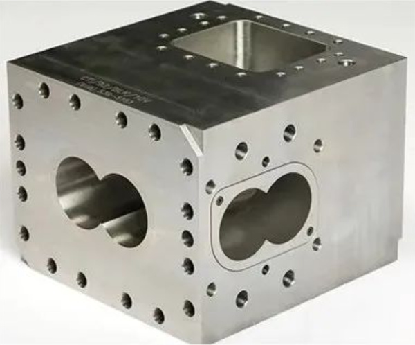
Opening machine barrel section
Some barrel designs provide the unique configuration of twin screw extruders. When we pair each barrel with an appropriate screw configuration, we will conduct a general and more in-depth study of each of these barrel types for unit operation specific to that part of the extruder.
Each barrel section has an 8-shaped channel through which the screw shaft passes. The open barrel has external channels to allow for feeding or discharging volatile substances. These open barrel designs can be used for feeding and exhaust, and can be placed anywhere in the entire barrel combination.
Feed
Obviously, the material must be fed into the extruder to start mixing. The feeding barrel is an open barrel designed to have an opening at the top of the barrel through which material is fed. The most common position for the feed drum is at position 1, which is the first barrel in the process section. The granular material and freely flowing particles are measured using a feeder, allowing them to fall directly into the extruder through the feed barrel and reach the screw.
Powders with low stacking density often pose challenges as air often carries falling powder. These escaping air blocks the flow of light powder, reducing the ability of the powder to feed at the required rate.
One option for feeding powder is to set two open barrels at the first two barrels of the extruder. In this setting, the powder is fed into barrel 2, allowing the entrained air to be discharged from barrel 1. This configuration is called a rear exhaust device. The rear vent provides a channel for air to be discharged from the extruder without obstructing the feed chute. With the removal of air, the powder can be fed more effectively.
Once the polymer and additives are fed into the extruder, these solids are transported to the melting zone, where the polymer is melted and mixed with the additives. Additives can also be fed downstream of the melting zone using side feeders.
Exhaust
The open tube section can also be used for exhaust; The volatile vapor generated during the mixing process must be discharged before the polymer passes through the die.
The most obvious position of the vacuum port is towards the end of the extruder. This exhaust port is usually connected to a vacuum pump to ensure that all volatile substances carried in the polymer melt are removed before passing through the mold head. The residual steam or gas in the melt can lead to poor particle quality, including foaming and reduced packing density, which may affect the packaging effect of the particles.
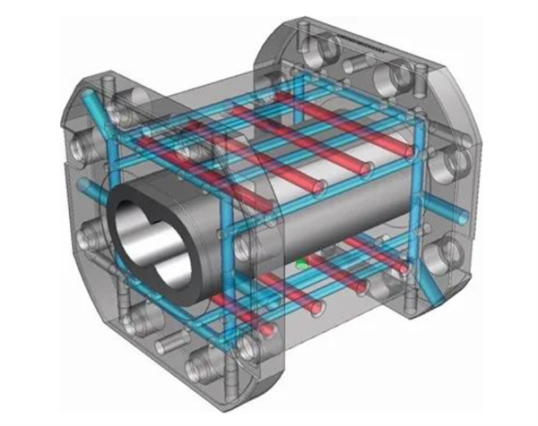
Closed barrel section
The most common cross-sectional design of the barrel is of course a closed barrel. The barrel part completely wraps the polymer melt on all four sides of the extruder, with only one 8-shaped opening that allows the center of the screw to pass through.
Once the polymer and any other additives have been fully fed into the extruder, the material will pass through the conveying section, the polymer will be melted, and all additives and polymers will be mixed. A closed barrel provides temperature control for all sides of the extruder, while an open barrel has fewer heaters and cooling channels.
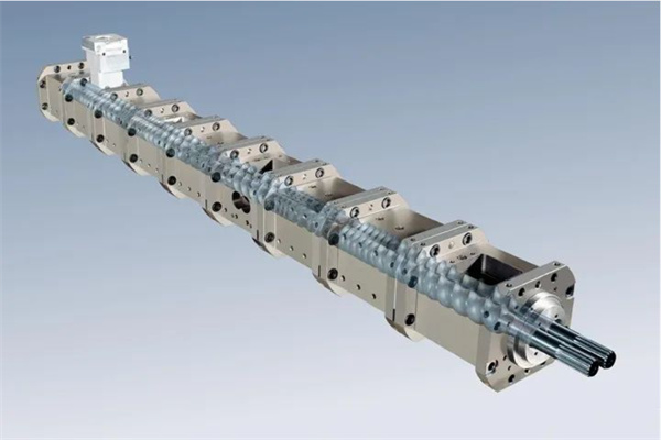
Assembling the extruder barrel
Typically, the extruder will be assembled by the manufacturer, with a barrel layout that matches the required process configuration. In most mixing systems, the extruder has an open feeding barrel in the feeding barrel 1. After this feeding section, there are several closed barrels used to transport solids, melt polymers, and mix melted polymers and additives together.
The combination cylinder can be located in cylinder 4 or 5 to allow for lateral feeding of additives, followed by several closed cylinders to continue mixing. The vacuum exhaust port is located near the end of the extruder, followed closely by the last closed barrel in front of the die head. An example of assembling the barrel can be seen in Figure 3.
The length of an extruder is usually expressed as the ratio of length to screw diameter (L/D). In this way, the enlargement of the process section will become easier, as a small extruder with an L/D ratio of 40:1 can be enlarged into an extruder with a larger diameter and a L/D length of 40:1.
Post time: Apr-04-2023